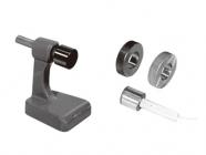
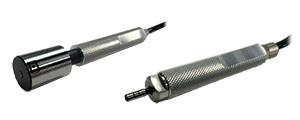
Sensor
ATC Run-Out Detection System
Aluminum High-Speed Cutting Process Monitoring Device
- How do chips in the tool chuck cause defects?
- Monitoring high-speed cutting of aluminum
- 0.3 second measuring time
- Low cost, integrated type
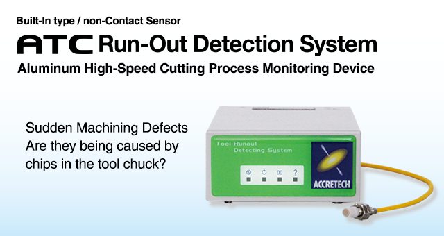
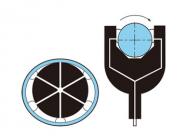
How do chips in the tool chuck cause defects?
 In an ATC machining center, defects can be generated during ATC when chips get into the space between the tool taper and the main spindle. For years, machining centers have looked for a solution to this problem, which is particularly prevalent during high-speed cutting of aluminum.

Monitoring high-speed cutting of aluminum
Because of shorter processing times, reductions in the amounts of coolants, and other
aluminum process demands, the frequency of chips getting into the tool taper during
ATC is increasing. During high-speed cutting of aluminum in particular, a measurement
instrument must be able to detect 100% of chip invasion into the tool taper, so
defects are not generated.
0.3 second measuring time
An eddy-current sensor allows measurement in a mere 0.3 seconds (at 600 rpm).
Since the measuring tool is selectable, measuring time is not affected by the cycle
time. A dedicated run-out detection system algorithm (patent pending) calculates true
run-out for detection capability that cannot be achieved by commercially available
eddy sensors. All of this means that the system delivers precise, reliable detection in
an automated line.
Low cost, integrated type
By connecting a PC to this device, you can set up parameters and collect
measurement data. This device need not be connected to a PC when
performing regular measurement. All NC communication has been incorporated
in to the OK/NG functions, which greatly reduces cost. Because
of all of this, this system is being adopted by many machine tool manufacturers
Specifications
| Type | Controller | AT50361 |
|---|---|---|
| φ 5 sensor | E-DT-ED10 (cable 10 m) | |
| Sensor installation range | 1.0±0.1mm from tool holder flange surface | |
| Measuring range | 1.0±0.2mm from tool holder flange surface | |
| Tool registration | 32 max | |
| Acceptable tools | BT30, BT40, BT50, HSK63A, etc. | |
| Performance | Display unit | 0.5 μm |
| Repeatability | 3 μm (2σ = 1.5 μm) *Using our master tool holder (BT40) | |
| Tool rotation Speed |
120, 600, 1200 rot/min | |
| Cycle time | 0.3 s (rotation speed 600 rot/min, without retries) | |
| Using environment |
Temperature | 0 to 40 ℃ |
| Vibration resistance |
3.66 G max. (x, y, z-axis directions) JIS C 60068-2-6 *Sweep 25 min at 10 to 15Hz (5 min per sweep) |
|
| Shock resistance |
Sensor head: 50 G max. (x, y, z-axis directions, 10 times) | |
| Controller: 20 G max. (x, y, z-axis directions, 10 times) | ||
| Waterproof standard |
IP67 (Sensor Head) *Do not expose controller to water , oil or other liquids. |
|
| Power requirements |
Nominal voltage |
DC24V±10% |
| Nominal power |
14 W | |
| Windows application operating environment and conditions |
Compatible machine |
PC with Windows 7 (32/64 bit), Windows 10 (32/64 bit) |
| Physical Memory |
128 MB or more (Windows 7 (32bit)) 1 GB or more (Windows 7 (32/64 bit), Windows 10 (32/64 bit)) |
|
| Disk space | 100 MB or more abailable disk space. | |
| OS | Windows 7 (32/64 bit), Windows 10 (32/64 bit) *Windows is a trademark of Microsoft Corporation in the United States. |
|
| Interface | One of RS-232C port COM1to COM16 is used. | |
●Standard system
| Product code |
Product name |
Model | Remarks |
|---|---|---|---|
| 0991012 | ATC Runout Detection System | AT50361 E-DT-ED10 |
Details: Controller, Φ 5 Sensor head 10 m, I/O cable 10 m, Power cable 10 m, Windows application CD, Operation manual (Japanese/English) per 2 copies, Inspection certificate 1 copy |
●Display unit
| Product code |
Product name |
Model | Remarks |
|---|---|---|---|
| 4220520 | Display unit set | AT50366 JPN-ENG |
Language: Japanese/English Details: Display unit, Power cable 10 m, USB memory 4 GB, Operation manual (Japanese/English) per 1 copy, Inspection certificate 1 copy |
| 4220611 | Display unit set | AT50366K KOR-ENG |
Language: Korean/English Details: Display unit, Power cable 10 m, USB memory 4 GB, Operation manual (Korean/English) per 1 copy, Inspection certificate 1 copy |
| 4220631 | Display unit set | AT50366C CHIN-ENG |
Language: Chinese/English Details: Display unit, Power cable 10 m, USB memory 4 GB, Operation manual (Chinese/English) per 1 copy, Inspection certificate 1 copy |
System configuration

Overview
Controller

Sensor head

Display unit

Precautions for sensor head mounting
Note 1: Do not extend or cut the sensor head cable.
Prepare a cable in an appropriate length by confirming the cable layout.
Use a two-way device when cutting the cable for connecting the terminal.
Note 2: Although the sensor head is tested in accordance with waterproofing
structure (Protective class IP 67) and anti-coolant characteristic test,
it does not mean that it is guaranteed for all type of coolant.
Note 3: Replaceable “Protective cap” is equipped in the sensor head for
abrasion protection against chips. Do not remove this “Protective cap”
when the system is operating.
Note 4: Use protective pipe for sensor head cables to protect from chips.
Maintain the cable bending more than R>35 mm (1.4” approx).
Note 5: Do not use the sensor head cable as it is wound.